TM 55-1520-240-23-6
7-334
BLEED UTILITY HYDRAULIC NO. 1 OR NO. 2 PTU MOTOR AND PUMP
(Continued)
7-334
Filter assembly kit
ADHT6814-M9716M must be
installed in test stand pressure
lines. Otherwise, system can be
contaminated.
NOTE
To operate hydraulic test stand, refer
to applicable manual.
NOTE
Procedure is same to bleed No. 1 or
No. 2 PTU motor and pump. No. 1
motor and pump is shown here.
1.
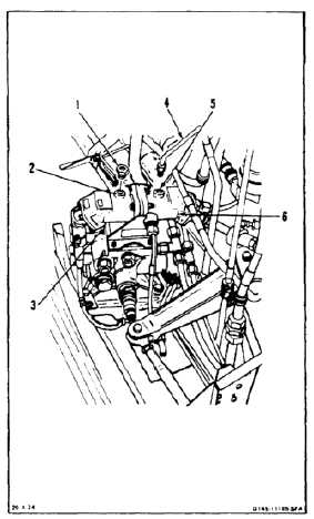
Remove plug (1) from port (2) of No. 1 PTU
motor (3).
2.
Fill pump (3) through port (2) with fluid (E199).
Use cloths (E120) for spilled fluid.
3.
Install plug (1) in port (2).
4.
Disconnect drain tube (4) from port (5) of pump
(6).
5.
Fill motor (6) through port (5) with fluid (E199).
Use cloths (E120) for spilled fluid. Use gloves
(E186).
6.
Connect tube (4) to port (5).
7.
Apply hydraulic power to flight system . Set test
stand to 300 psi.
8.
Apply hydraulic power to utility system. Slowly
increase pressure until motor (3) rotates. Have
helper on forward right work platform listen for
motor rotation. Allow pump to rotate for about 3
minutes.
9.
Remove hydraulic power from flight and utility
systems.
FOLLOW-ON MAINTENANCE:
Set POWER XFER NO. 1 switch on hydraulic panel
to OFF.
Disconnect hydraulic test stands from ground service
panel (Task 1-38).
Remove electrical power (Task 1-37).
Close right forward work platform or pylon right
access door (Task 2-2).
END OF TASK
7-1230


