TM 55-1520-240-23-6
7-307
ADJUST POWER STEERING OUT-OF-PHASE SWITCH
(Continued)
7-307
ADJUST SWITCH
4.
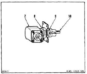
Remove lockwire from jam nuts (8 and 9).
5.
If switch (2) activates early, turn each nut (8 and
9) an equal amount away from roller (10), no
more than one flat.
6.
If switch (2) activates late, turn each nut (8 and
9) an equal amount toward roller (10), no more
than one flat.
7.
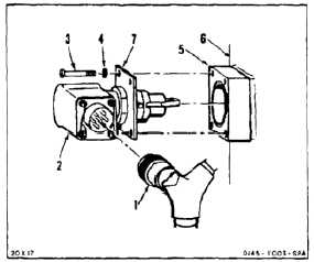
Install switch (2) and plate (7) as a unit on spacer
(5). Install four screws (3) and washers (4).
8.
Connect electrical connector (1).
9.
Perform an operational test of switch (2) (TM
55-1520-240-T). If test is good, go to step 15. If
test is not good, go to step 10.
NOTE
Lockwire removal is not needed for
repeated steps.
10.
Disconnect battery (Task 1-39).
11.
Repeat steps 1 thru 9. Install switch.
12.
Repeat steps 1 and 3.
13.
Lockwire jam nut (9) to lockring (11).
14.
Install switch (2) and plate (7) as a unit spacer
(5). Install four screws (3) and washers (4).
7-1112


