TM 55-1520-240-23-6
7-306
INSTALL POWER STEERING OUT-OF-PHASE SWITCH
(Continued)
7-306
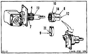
5.
Install guide (8) on shaft (4) until guide bottoms
out. Turn guide back to align guide clevis with
shaft slot as shown.
6.
Install lockring (9) in groove (10) of guide (6).
Align pin (11) with guide clevis (12) and shaft slot
(13). Make sure pin seats in groove hole (14).
7.
Lockwire lockring (9) to nut (7). Use lockwire
(E231) through both holes of lockring.
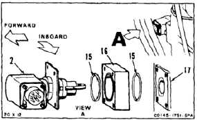
8.
Install two packings (15), spacer (16), and switch
(2). Position switch against actuator (17) and
align holes as shown.
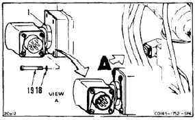
9.
Install four washers (18) and screws (19).
10.
Lockwire screws (19) to nut (1). Use lockwire
(E231).
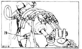
11.
Connect cable plug (20) to switch (2).
INSPECT
FOLLOW-ON MAINTENANCE:
Perform operational check of out-of-phase switch (TM
55-1520-240-T).
Close aft right landing gear access panel (Task 2-2).
END OF TASK
7-1110