TM 55-1520-240-23-6
7-268.1
ASSEMBLE 145HS775 RAMP CONTROL VALVE (AVIM)
(Continued)
7-268.1
NOTE
If replacement of a solenoid valve
is necessary, replacement of the
connector may also be required if
sealing compound around wires,
diodes, and connector cannot be
properly cleaned away.
44.
Install new solenoid valve as follows:
a.
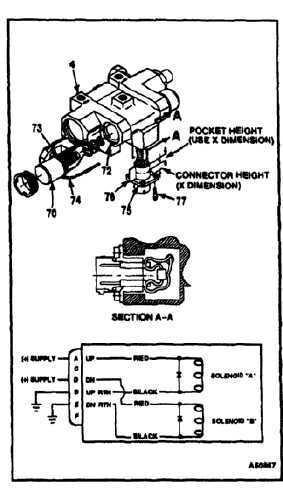
Feed wires (74) through passage (72) in
valve body (4) to connector (75), and install
solenoid(s) (70) as described in steps 39 thru
43. Make sure pin (73) of solenoid housing
(70) aligns with hole in valve body (4).
b.
Solder wires and diode(s) to appropriate pins
of connector (75).
c.
Wrap masking tape (76) around back of
connector (75). Form a pocket as high as
the back of the connector, around wires and
diodes.
d.
Fill pocket with sealant (E332.1 or E332.2)
and wait until sealant sets up enough to
maintain its shape.
e.
Peel off masking tape (76), and immediately
install connector (75), forcing sealant and
connector into cavity of valve body (4).
f.
Lubricate and install four screws (77). Torque
screws 15 to 20 inch-pounds.
g.
Lockwire screws (77). Use lockwire (E229).
45.
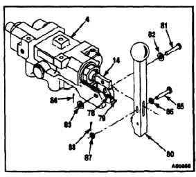
Lubricate spring (78) and detent ball (79) with
hydraulic fluid (E199).
46.
Install spring (78), detent ball (79), and handle
(80) in valve body (4) between arms of valve
body. Hold handle in place.
47.
Install pin (81), washers (82 and 83), and cotter
pin (84) through arms of valve body (4) and
handle (80).
48.
Install pin (85), washers (86 and 87), and cotter
pin (88) through handle (80) and clevis of input
piston (14).
INSPECT
FOLLOW-ON MAINTENANCE:
Test ramp control valve (Task 7-269.1).
END OF TASK
7-992