TM 55-1520-240-23-6
7-268.1
ASSEMBLE 145HS775 RAMP CONTROL VALVE (AVIM)
(Continued)
7-268.1
29.
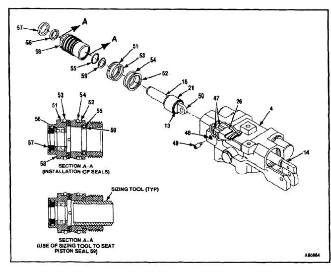
Install rod piston assembly (15) as follows:
a.
Slide input piston (14) towards far end of
valve body (4) until attachment flanges (47)
of slide assembly (26) can be seen through
port (48) in valve body.
b.
Slide floating piston (21) on rod piston (15)
back until retainer seats against seal flange
(13).
c.
Lubricate pin assembly (49) with hydraulic
fluid (E199).
d.
Install rod piston (15) with clevis (50) between
flanges (47) of slide assembly (26). Looking
through port (48) of valve body (4), line up
hole in clevis with holes in flange of slide
assembly and hold in postition.
e.
Install pin assembly (49) through port (48),
and into flanges (47) of slide assembly (26),
and clevis (50) of rod piston (15). Torque pin
assembly 15 to 20 inch-pounds.
30.
Lubricate and install backup rings (51 and 52),
packings (53, 54, and 55), T ring (56), and gland
seal (57), on gland nut (58).
31.
Lubricate and carefully install piston (cap) seal
(59) over packing (55) inside gland nut (58).
Lubricate sizing tool (T177) with hydraulic fluid
(E199) and slide sizing tool into gland nut to seat
piston (cap) seal over packing.
32.
Lubricate shaft of rod piston (15), gland seal
(57), T ring (56), piston (cap) seal (59), and
internal surfaces of valve body (4) with hydraulic
fluid (E199).
33.
Install gland nut (58) and torque 195 to 215
inch-pounds.
34.
Lockwire gland nut (58) to valve body (4). Use
lockwire (E229).
7-990


