TM 55-1520-240-23-6
7-268.1
ASSEMBLE 145HS775 RAMP CONTROL VALVE (AVIM)
(Continued)
7-268.1
12.
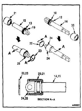
Install floating pistons (20 and 21) on input and
rod pistons (14 and 15) as follows:
a.
Lubricate input and rod pistons (14 and 15),
floating pistons (20 and 21), and piston seals
(18 and 19) with hydraulic fluid (E199).
b.
Slide floating pistons (20 and 21) over input
and rod pistons (14 and 15), until floating
pistons contact seal flanges (12 and 13).
Flanged end of floating pistons shall face
opposite end of clevises of input and rod
pistons.
13.
Lubricate retainers (22 and 23) with hydraulic
fluid (E199) and install retainers in seats (24 and
25) of floating pistons (20 and 21).
14.
Lubricate rod piston assembly (15), and place in
clean plastic bag (E78) or wrap in barrier material
(E80) until needed.
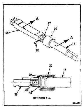
15.
Connect slide assembly (26) to clevis (27) of
input piston (14) as follows:
a.
Move floating piston (20) towards handle end
of input piston (14) until retainer (22) seats
against seal flange (12).
b.
Fit clevis (27) of input piston (14) between
flanges at grooved end of slide assembly
(26).
c.
Install pin assembly (28) lubricated with
hydraulic fluid (E199), through flanges of slide
assembly (26), and clevis of input piston (14).
d.
Torque pin assembly (28) 15 to 20
inch-pounds.
7-988


