TM 55-1520-240-23-5
6-10.1
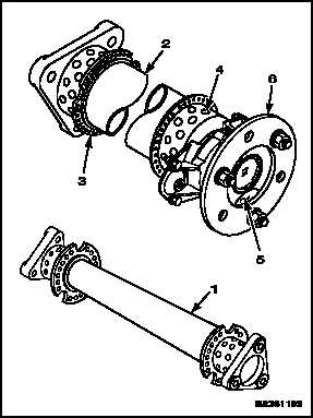
CLEAN AND INSPECT DRIVE SHAFTING OFF AIRCRAFT (Continued)
6-10.1
NOTE
Inspect all drive shafts in the same
way. Typical shaft shown.
Rotate shaft as needed to complete
check.
Tube and adapter are balanced
together. If one is damaged, both
must be replaced.
1.
Inspect shaft (1) for damage listed below. There
shall be no such damage.
a.
Cracks in tube (2).
b.
Dents in tube (2) more than 1 inch diameter
or 0.040 inch deep.
c.
Distance between any two dents less than
4.5 inches.
d.
More than one dent around tube (2) at any
one point.
e.
Distance between end flange (3) and any
dent less than 1.25 inches.
f.
Loose or cracked rivets (4) at ends of tube.
NOTE
Adapters have a shotpeened surface.
Damage cannot be repaired.
g.
Cracks, nicks, scratches, or gouges in
adapter (5). Use a 5X magnifying glass to
check.
h.
Cracks in plates (6). Use 5X magnifying
glass to check.
i.
Nicks on inside edge of plates (6). Use a
pointed scribe to check.
j.
Cracks, nicks, scratches or gouges in dents
in tube (2). Use Fluorescent Inspection to
check (TM 1-1500-335-23).
k.
Inspect for corrosion. If no corrosion is found,
perform only steps 2 and 3.
NOTE
Vibro-engraved factory markings on
tube are allowed.
2.
Inspect for nicks, scratches, or gouges in tube (2)
or plates (6). Repair damage (Task 6-11).
3.
Visually inspect tubes (2) for circumferential
scoring. Observe following limits:
a.
Depth after blending: 0.010 inch maximum.
b.
Length after blending: 2.0 inches maximum.
c.
Width after blending: 0.40 inch maximum.
d.
Minimum distance from adapter rivets is: 7
inches, each end.
e.
Minimum axial distance between
circumferential scoring repairs is 4.5 inches.
f.
Maximum of one circumferential scoring
repair around tube outer diameter (OD) at
any one point.
Change 1
6-35