TM 55-1520-240-23-3
4-122
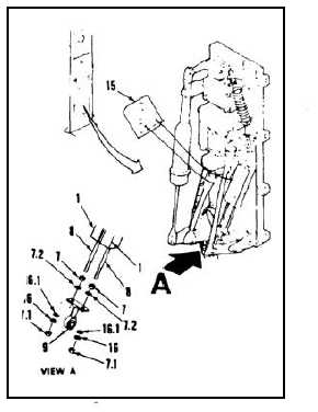
INSTALL AND RIG ENGINE DROOP ELIMINATOR VARIABLE RESISTORS
(Continued)
4-122
6.
Remove two nuts (7.1) and two washers (16).
7.
Adjust shaft (8) until multimeter (15) reads 30
to 35 ohms.
8.
Install two washers (16), two lockwashers
(16.1) and two nuts (7.1). Torque nuts to 25
inch-pounds. Check nuts for thread protrusion.
If all threads on nut are not engaged, replace
engine droop eliminator variable resistors (1)
(Tasks 4-119 and 4-122).
9.
Tighten two nuts (7) against link (9). Torque nuts
to 25 inch-pounds. Make sure link (9) is parallel
to resistor shafts (8).
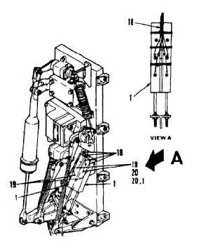
NOTE
Use the following hardware to
connect wiring to resistors: screws
MS35275-202, washers AN960C3L,
and lockwashers MS35340-39 or
equivalent.
10.
Remove tape from ends of eight wires (18).
Connect eight wires to resistors (1) by installing
eight screws (19), eight lock washers (20), and
eight washers (20.1). Remove tags from wires.
11.
Secure wires (18) to resistors (1). Use twine
(E433).
FOLLOW-ON MAINTENANCE:
Adjust engine droop eliminator variable resistors
(Task 4-118).
Install controls closet panel (Task 2-2).
Install controls closet acoustic blanket (Task 2-108).
END OF TASK
4-426