TM 55-1520-240-23-3
4-37
INSPECT AFT ENGINE MOUNT LINK AND ADAPTER PARTS
(Continued)
4-37
INSPECT AFT ENGINE MOUNT LINK AND ADAPTER
WITH 57
11.
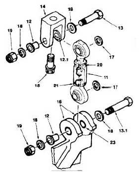
Clean link (11), four bushings (12, 12.1, and 23),
two bolts (13 and 13.1), adapter (14), adapter
bolt (15), and aft engine mount lugs (16) on
structure. Use solvent (E162) and cloth (E135).
Wear gloves (E186.1).
12.
Inspect link (11), four bushings (12, 12.1, and
23), two bolts (13 and 13.1), bolt (15), and
adapter (14). There shall be no cracks, gouges,
scratches, or dents, which exceed 10 percent
of material thickness or 0.040 inch. Whichever
is less. If a crack is suspected in the aft engine
mount link or the aft engine mount, refer to TM
1-1520-253-23.
13.
Inspect lockwire on engine mount link for breaks.
14.
Inspect torque stripe of link body and jam-nuts
(21) for breaks.
NOTE
During the inspection of the aft
engine mount lugs, inspect for cracks
originating from the inboard lug recess
at the bolt hole.
15.
Inspect lugs (16) on structure. There shall be
no cracks, gouges, scratches, or dents deeper
than 0.040 inch.
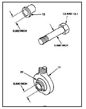
16.
Measure inside diameter of four bushings (12).
Diameter shall not be more than 0.502 inch.
17.
Measure inside diameter of two bearings (22).
Bearing diameter shall not be more than 0.500
inch.
18.
Measure shank diameter of two bolts (13 and
13.1). Diameter shall not be less than 0.495
inch.
19.
Use a dial indicating scale to apply a 25 to 50
pound load to bearing (22) in axial direction.
Apply a 25 to 50 pound load to bearing (22) in
opposite direction. Measure axial play. Play shall
not be more than 0.006 inch.
20.
Apply a 25 to 50 pound load to bearing (22) in
radial direction. Apply a 25 to 50 pound load to
bearing (22) in opposite direction. Measure radial
play. Play shall not be more than 0.006 inch.
21.
Repeat steps 19 and 20 four times for each
bearing (22). Rotate bearing 90º each time.
FOLLOW-ON MAINTENANCE:
None
END OF TASK
4-199