TM 55-1520-240-23-3
4-36
REMOVE AFT ENGINE MOUNT LINK AND ADAPTER
4-36
INITIAL SETUP
Applicable Configurations:
All
Tools:
Aircraft Mechanic’s Tool Kit, NSN 5180-00-323-4692
Hoist
Sling
Materials:
Paper Tags (E264)
Personnel Required:
Medium Helicopter Repairer (2)
Equipment Condition:
Battery Disconnected (Task 1-39)
Electrical Power Off
Engine Work Platform Open (Task 2-2)
Engine Side Access Doors Open (Task 4-49)
Engine Lower Access Door Opened (Task 4-49)
For helicopters without 57 make
sure bearing in lower end of link
does not tilt within clevis while
weight of engine is supported. If
bearing tilts it will wedge in clevis
and damage bearing and clevis.
Do not stretch or stress hoses and
electrical harnesses attached to
helicopter, when supporting engine
weight. Stress or stretching can
damage hoses and harnesses.
NOTE
For helicopters with 57 adjustable link
145PS700-1 is adjusted to set engine
cross shaft alignment at the time of
aircraft manufacture or incorporation
of MWO 1-1520-240-50-60. The
adjustment fixtures are unique and
are not interchangeable.
This preserves the proper link length
measurement for each engine should
the link need to be replaced or
adjusted.
Aft engine mount links that have been
modified by 57 with adjustable link
145PS700-1 must not be replaced
with fixed link 114PS223-1.
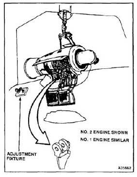
This procedure can be used to remove
aft engine mount link and adapter on
either engine. Link and adapter on
No. 2 engine are shown here.
As a result of applying 57 MWO
1-1520-240-50-60, new adjustable
link 145PS700-1 becomes part of the
airframe and should not be removed
to support engine on trailer adapter
(T16) MWO 1-1520-240-50-60
provides instructions to permanently
mount old one piece link 114PS223-1
to trailer adapter (T16) to provide
support for the engine.
4-194


