TM 55-1520-240-23-3
4-14
PERFORM ENGINE VIBRATION TEST
(Continued)
4-14
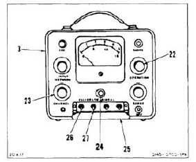
ADJUST METER
NOTE
Vibration pickup transducer part
number CFC4-118-0107 is calibrated
at 10.5. If vibration pickup transducer
part number CEC4-128-0101 is used,
calibrate it at 6.0.
16.
Set OPERATION selector (22) to C. Pointer shall
move toward right side of scale.
17.
Set CHANNEL selector (23) to 1.
18.
Push in CALIBRATE SIGNAL control (24). Adjust
control until meter (3) indicates 10.5.
19.
Slowly release control.
20.
Open panel (25). Adjust SENSITIVITY 1 control
(26) until meter indicates 15.0.
21.
Push in CALIBRATE SIGNAL control (24). Meter
shall indicate 10.5.
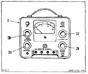
22.
Slowly release control (24). Meter shall indicate
15.0.
23.
Set CHANNEL selector (23) to 2.
24.
Repeat steps 19 and 20.
25.
Adjust SENSITIVITY 2 control (27) until meter
(3) indicates 15.0.
26.
Push CALIBRATE SIGNAL control (24). Meter
(3) shall indicate 10.5.
27.
Release control (24). Meter (3) shall indicate
15.0.
PERFORM TEST
28.
Set INPUT NETWORK selector (28) to 70.
29.
Set OPERATION selector (22) to VX1.0.
30.
Set RANGE selector (29) to 5.
31.
Set CHANNEL selector (23) to 1.
32.
Observe meter (3) during test. Average velocity
shall not exceed 1.2 inches per-second.
4-121