TM 55-1520-240-23-3
4-12
ASSEMBLE POWERPLANT
(Continued)
4-12
5.
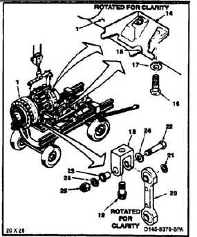
Position two adapters (14) so holes in adapters
align with holes in powerplant (1). Make sure
curved surfaces (15) of adapters are down.
Shipping and mounting hardware are
similar. Ensure correct hardware is
used during powerplant assembly.
Otherwise, damage to powerplant and
aircraft as wail as injury to personnel
may occur.
6.
Install eight bolts (16) and washers (17). Torque
bolts to 300 to 450 inch-pounds. Lockwire
bolts. Use lockwire (E231).
7.
Position adapter (18) on powerplant (1) and
install bolt (19). Torque bolt to 400 inch-pounds.
Lockwire bolt. Use lockwire (E231).
8.
Align hole in link (20) and spacer (21) with holes
in adaptor (18). Install bolt (22), bushing (23),
two washers (24), and nut (25). Torque nut (25)
to 375 inch-pounds to seat bushing. Loosen nut
and retorque to 20 inch-pounds above run on
torque. Not to be less than 70 inch-pounds.
9.
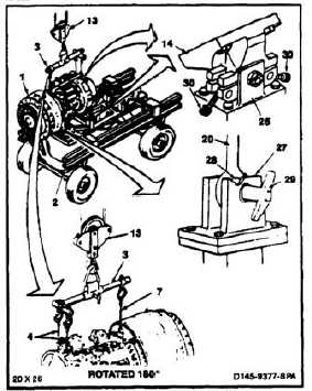
Position powerplant (1) over powerplant adapter
(T16). Make sure forward engine mount adapters
(14) and aft link (20) align with adapter fittings
(26 and 27).
During lowering of powerplant to
adapter, make sure bearing in aft
engine mount link does not tilt in clevis
of adapter fitting. If bearing tilts, it will
wedge in clevis, causing damage to
bearing and clevis.
10.
Lower hoist (13) slowly until powerplant (1)
weight is on adapter (2). Make sure bearing (28)
in aft mount link (20) does not tilt or wedge in
clevis of adapter fitting (27).
11.
Install pin (29) through link (20) and adapter
fitting (27).
12.
Raise four bolts (30) over engine mount adapters.
Tighten bolts.
13.
Disconnect hoist (13) from sling (3).
14.
Disconnect three cables (4 and 7) and remove
sling (3).
4-95


