TM 55-1520-240-23-7
8-58
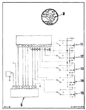
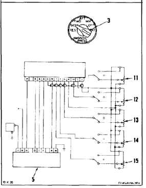
TEST TRANSMISSION OIL PRESSURE SELECTOR SWITCH OR INDICATOR
(AVIM)
(Continued)
8-58
RESPONSE TEST
26.
Set selector switch knob (3) to SCAN. Adjust
FWD resistor (11) until indicator (5) reads 30 psi.
27.
Adjust AFT resistor (12), MIX resistor (13), LEFT
resistor (14), and RIGHT resistor (15) clockwise
to 3500 ohms (7 turns).
28.
Adjust AFT resistor (12) clockwise until pointer
of indicator (5) moves upscale then downscale.
Check upscale movement of pointer. Upscale
movement of pointer shall be less than 1 psi.
Adjust AFT resistor to setting recorded in step 27.
29.
Repeat steps 27 and 28 at MIX (13), LEFT (14),
and RIGHT (15) resistors. Then go to step 30.
SCALE ERROR TEST
30.
Set selector switch knob (3) to SCAN.
31.
Adjust resistors (11, 12, 13, 14, and 15) to 100
percent (full counterclockwise).
32.
Adjust FWD resistor (11) clockwise. For indicator
(5) readings listed, resistor settings shall be
within tolerance as follows:
NO BREAK - WORK HARDER
SET INDICATOR
READING TO
VARIABLE RESISTOR
SETTING SHALL BE
95 psi
93.5 to 96.5 percent
80 psi
78.5 to 81.5 percent
60 psi
58.5 to 61.5 percent
40 psi
38.5 to 41.5 percent
20 psi
18.5 to 21.5 percent
0 psi
0 to 1.5 percent
8-170