TM 55-1520-240-23-5
6-186
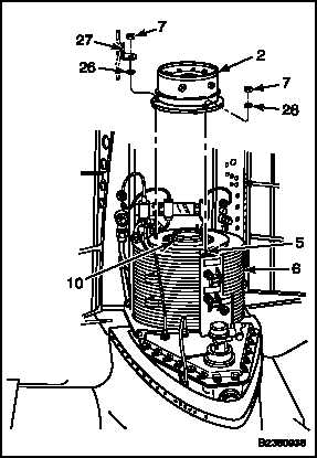
INSTALL COMBINING TRANSMISSION OIL COOLER FAN AND SHAFT 145D5319-3 OR
-5 (Continued)
6-186
10.
Install fan (2) as follows:
a.
Coat four studs (5) with oil (E253, E254, or
E254.1).
b.
Lower the fan onto the studs. Lightly tap the
fan to seat it on oil cooler (6). Use a rawhide
mallet.
WARNING
Do not use mounting nuts to jack the
fan down against the oil cooler. This
pressure will load the bearing if there
is too much grease.
c.
If the fan cannot be seated by tapping,
remove it, being careful to hold shaft (10) in
place at the transmission end to prevent the
shaft from being removed with the fan. Wipe
the grease from the first 0.5 inch of the cavity
in the splined shaft of the fan. Repeat steps a
thru c to reinstall the fan.
d.
Check for gaps under flange of the fan as in
step 6. Compare with gaps noted in step 6.
If any gap has increased, remove the fan.
Reinstall the fan (steps a thru c).
e.
Again, check and compare gaps as in step
d. If any gap is still greater than measured in
step 6, remove the fan and shaft (10). Repeat
installation from step 3.
f.
When the fan is seated, install washers (26),
bracket (27) (at one stud only), and nuts (7)
on studs (5). Torque the nuts (7) to 100-140
inch-pounds.
6-610
Change 1