TM 55-1520-240-23-3
4-140
INSTALL AND RIG POWER TURBINE CONTROL LINKAGE
(Continued)
4-140
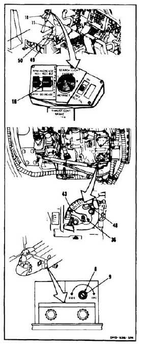
22.
Remove rigging pin (11) from hole (49) in floor
(50). Set thrust control (10) to detent position.
23.
Have helper hold No. 1 & 2 switch (16) to RPM
INCREASE for 8 to 10 seconds.
24.
Check pointer (36). Pointer shall contact N2
RPM limiting stop (48).
25.
Have helper hold switch (16) to RPM DECREASE
for 8 to 10 seconds. Index mark (43) on pointer
(36) shall be between 19º and 21º. If pointer is
not between 19º and 21º, rotate resistor shaft (9)
until pointer is at 20º.
26.
Tighten locknut (8).
FOLLOW-ON MAINTENANCE:
Install forward floor panels (Task 2-82).
Close left electrical compartment access door (Task
2-2).
Perform operational check of power turbine system
(TM 55-1520-240-T).
Close engine access cover (Task 4-50).
Close engine work platform (Task 2-2).
Electrical power off.
Hydraulic power off.
Disconnect battery (Task 1-39).
END OF TASK
4-461/(4-462 blank)