TM 55-1520-240-23-3
4-129
ADJUST MINIMUM ROTOR RPM
(Continued)
4-129
NOTE
See TM 55-1520-240-10 for
operational procedures performed by
pilot.
1.
Have pilot set thrust control to ground detent.
2.
Have pilot set NO. 1 & NO. 2 ENGINE BEEP trim
switch to RPM DECREASE for 8 seconds.
3.
Have pilot operate No. 1 engine in FLIGHT.
4.
If minimum rotor rpm is 91 to 94 percent, go to
step 6. If not, go to step 5.
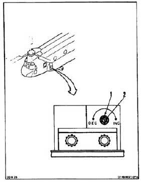
Do not force resistor at either limit of
its range. Internal damage to resistor
can result.
NOTE
Variable resistor for No. 1 engine is in
left electrical compartment. Variable
resistor for No. 2 engine is in right
electrical compartment.
Turning shaft clockwise will increase
rotor rpm . Counterclockwise
adjustment will decrease rotor rpm.
5.
Loosen nut (1) on variable resistor shaft (2).
Adjust resistor shaft slowly until rotor rpm is 92.5
percent. Tighten nut. Make sure rotor rpm is
92.5 percent.
6.
Have pilot shut down No. 1 engine.
4-434