TM 55-1520-240-23-9
11-106
INSTALL YAW, THRUST OR ROLL CONNECTING LINKS OR PITCH, YAW, THRUST OR
ROLL INPUT LINKS BETWEEN STA 95 AND STA 120
(Continued)
11-106
Rotary-wing heads must not be
turned; otherwise, damage to
components will result.
Do not move cockpit thrust control;
otherwise, damage to components
will result.
Bushings must be in bellcranks before
installing bolts; otherwise, damage to
components will result.
NOTE
Procedure is same to install yaw,
thrust, or roll connecting links, or
pitch, yaw, thrust or roll input links.
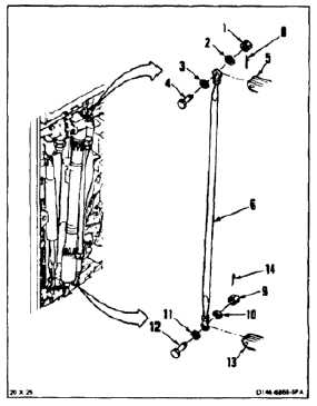
Thrust connecting link is shown here.
Impedance bolts are installed in flight
control connections. These bolts are
self-retaining and require a special
nut and torque (Task 1-13).
1.
Remove nut (1), two washers (2 and 3), and bolt
(4) from bellcrank (5).
FLIGHT SAFETY PARTS
This is an installation critical flight
safety part. All aspects of its assembly
and installation must be ensured.
Ensure that both rod end jam nuts are
installed and torqued.
Ensure that the rivet through the fixed
rod end bearing is secure.
Ensure proper attaching hardware
(impedance type bolt, nut, and
washers) is installed including
verification of bolt head orientation,
torque, and installation of cotter pins.
Loose attachments within flight control
secondary linkage will degrade
aircraft control. Missing components
will cause loss of control.
2.
Position thrust connecting link (6) in bellcrank (5)
with inspection hole (7) to bellcrank. Install bolt
(4), two washers (2 and 3), and nut (1).
3.
Torque nut (1) to 30 to 45 inch-pounds. Install
cotter pin (8).
4.
Remove nut (9), two washers (10 and 11), and
bolt (12) from bellcrank (13).
5.
Position link (6) in bellcrank (13). Install bolt (12),
two washers (11 and 10) and nut (9).
6.
Torque nut (9) to 30 to 45 inch-pounds. Install
cotter pin (14).
7.
Check two bolts (4 and 12). Bolts shall not rotate
with torque less than 10 inch-pounds. There
shall be no axial looseness. If bolts rotate or are
loose, add washer under nut and repeat step 3
or 6.
INSPECT
11-531