TM 55-1520-240-23-9
11-54
RIG FORWARD OR AFT SWASHPLATE AND SERVOCYLINDERS
(Continued)
11-54
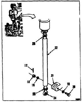
ADJUST SERVOCYLINDER CONNECTION LINK
Death or serious injury may occur
if the correct procedures are not
followed when removing the upper
rod end bolt to the pilot valve with
hydraulic power applied to any of the
servocylinders.
NOTE
Procedure is same to adjust forward
or aft left or right servocylinder
connecting link. Left forward
connecting link is shown here.
7.
Remove cotter pin (17), nut (18). washers (19),
and bolt (20) from bellcrank (21). Disconnect
forward left connecting link (22) from bellcrank.
NOTE
One-half turn of bearing or connecting
link moves servocylinder pistons 0.02
inch.
8.
Loosen nut (23). Turn bearing (24). If bearing
will not turn, loosen nut (25), end turn connecting
link (22). Torque nuts (23 end 25) to 103
inch-pounds.
9.
Position link (22) in bellcrank (21). Install
washers (19) bolt (20), end nut (18). Torque nut
(18) to 30 inch-pounds. Continue tightening
only as needed to align cotter pin holes. Do not
exceed 45 inch-pounds. Install cotter pin (17).
10.
Deleted.
11-243