TM 55-1520-240-23-9
11-49
RIG PALLET PITCH AND ROLL IDLER BELLCRANKS
(Continued)
11-49
6.
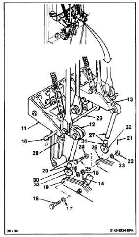
Remove cotter pin (14), nut (15), two washers
(16 and 17), and bolt (18) from thrust transfer
bellcrank (19). Disconnect thrust input link (20)
from bellcrank.
7.
Remove cotter pin (21), nut (22), two washers
(23 and 24), and bolt (25) from yaw transfer
bellcrank (26). Disconnect role input link (27)
from bellcrank.
8.
Install pin (10) through support (11) and two
bellcranks (12 and 13). Pin must slide freely. If
not repeat steps 1, 8, and 3 then go to 9.
9.
Adjust yaw position transducer (28) (Task
11-176).
10.
Loosen nut (30) of link (20). Turn rod end (30)
until link can be positioned in bellcrank (19) with
bolt (18) installed loosely.
Bushings must be in bellcranks before
installing bolts; otherwise, damage to
components will result.
11.
Install bolt (18), two washers (17 and 16), and
nut (15) in bellcrank (19). Do not torque nut at
this time.
12.
Loosen nut (31) of link (27). Turn rod end (32)
until link can be positioned in bellcrank (26) with
bolt (25) installed loosely.
13.
Install bolt (25), two washers (24 and 23), and
nut (22) in bellcrank (26).
14.
Torque two nuts (15 and 22) to 30 to 45
inch-pounds. Install two cotter pins (14 and 21).
15.
Torque two nuts (29 and 31) to 30 to 40
inch-pounds.
16.
Check two bolts (18 and 25). Bolts shall not
rotate with torque less than 10 inch-pounds.
There shall be no axial looseness. If bolt rotates
or is loose add washer under nut and repeat
step 14.
17.
Remove pin (10) from support (11).
11-207