TM 55-1520-240-23-9
11-34
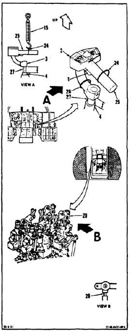
ARTIFICIAL FEEL FORCES CHECK
(Continued)
11-34
THRUST CONTROL
48.
Press switch (1) of control (2). Raise control to
about 6.3 inches measured between grip (3) and
pivot block (4). Lower to detent position. Tape
switch in pressed position. Use tape (E388).
49.
Install strap (24) loose on grip handle (25).
50.
Install strap (26) loose on grip (3) close to shaft
(27).
51.
Attach scale (15) to strap (24).
52.
Have helper in passageway check output rod
(28) of thrust ILCA (29) for movement.
53.
Align scale (15) with shaft (27). Apply force up at
handle (25). Measure force when rod (28) starts
to move. Force must be 2.0 to 7.0 pounds.
54.
Remove scale (15) from strap (24). Attach scale
to strap (26).
55.
Position scale (15) down and parallel to shaft
(27). Apply force down at handle (25). Measure
force when rod (28) starts to move. Force must
be 5.0 to 15.0 pounds.
56.
Remove scale (15) from strap (26). Attach scale
to strap (24).
57.
Align scale (15) with shaft (27). Apply force up at
handle (25). Measure force until rod (28) stops
moving. Force must be 5.0 to 9.0 pounds.
58.
Raise control (2) to 5.5 inches measured
between grip (3) and pivot block (4).
59.
Repeat step 53. Force must be 1.0 to 4.0
pounds.
60.
Repeat step 58.
61.
Repeat step 54.
62.
Repeat step 55. Force must be 1.0 to 4.0
pounds.
63.
Check force measured in step 59 must be equal
to force measured in step 62 within 1.5 pounds.
11-127