TM 55-1520-240-23-9
11-277
BENCH TEST AFCS COMPUTER (AVIM)
(Continued)
11-277
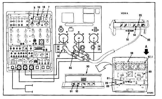
The case leak valve levers must be
in these positions, and the safety
valve closed, to isolate the airspeed
indicator from the vacuum source;
otherwise, damage to the instrument
can occur.
794.
Open cover (90).
795.
Set lever (91) to NOR and lever (92) to CL. Close
cover (90).
796.
Turn knob (93) fully clockwise.
797.
Remove cap (94) from fitting (95).
Hose assembly must be connected to
both pitot and static ports; otherwise,
damage to airspeed differential
pressure transducer can occur.
798.
Connect hose (96) (APP E-37) to fitting (95), port
S (97), and port P (86).
798.1. Set pressure knob (80) to MANIFOLD
PRESSURE.
798.2. Check MANIFOLD PRESSURE indicator (97.1).
Indicator shall read 30 (sea level). Adjust
pressure if necessary (TM 55-4920-378-14).
799.
Set CIRCUIT SELECT TENS switch (8) to 60.
800.
Set CIRCUIT SELECT A UNITS switch (18) to 3.
801.
Set METER RANGE switch (7) to 200MV.
802.
Set power switch (81) to ON. Read AC/DC
VOLTMETER (10). Reading shall be -0.05 to
+0.05.
803.
Slowly turn INCREASE knob (88)
counterclockwise until ALT indicator (98)
reads 1000 feet. Turn knob fully clockwise.
11-1142


