TM 55-1520-240-23-9
11-265
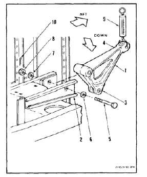
INSTALL PYLON LEFT UPPER BELLCRANK
(Continued)
11-265
c.
Check that torque on nut (8) is more than 155
inch-pounds with cotter pin hole aligned.
d.
Repeat step a.
4.
Install cotter pin (10).
NOTE
The adjustable rod ends should be
aft or up.
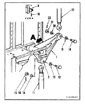
INSPECT
5.
Untie connecting link (11). Position link in short
arm (3) of bellcrank (1). Install bolt (12), two
washers (13 and 14), and nut (15).
6.
Torque nut (15) to 60 to 90 inch-pounds. Install
cotter pin (16).
7.
Position connecting link (17) in bellcrank (1).
Install bolt (18), two washers (19 and 20) and
nut (21). Remove tag.
8.
Torque nut (21) to 30 to 45 inch-pounds. Install
cotter pin (22).
9.
Check two bolts (12 and 18). Bolts shall not
rotate with torque less than 10 inch-pounds.
There shall be no axial looseness. If bolt rotates
or is loose, add washer under nut and repeat
step 6 or 8.
NOTE
If the connecting links are changed
in length, perform neutral rig check
(Task 11-33).
INSPECT
NOTE
Inspect bellcrank and connecting link
bearings (Task 11-9).
FOLLOW-ON MAINTENANCE:
Connect servocylinder connecting links (Task
11-193).
Remove safety blocks (Task 11-29).
Close pylon left work platform (Task 2-2).
Close cargo ramp (Task 2-2).
END OF TASK
11-1006