TM 55-1520-240-23-9
11-265
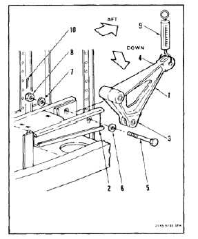
INSTALL PYLON LEFT UPPER BELLCRANK
(Continued)
11-265
FLIGHT SAFETY PARTS
This is an installation critical flight
safety part. All aspects of its assembly
and installation must be ensured at
each joint connection and mounting to
the airframe.
Ensure that all bushings are properly
installed (including orientation) in
each input and output clevis of the
bellcrank.
Ensure bellcrank hub bearings are
serviceable and properly installed.
Ensure proper orientation of bellcrank
at installation.
Ensure proper attaching hardware
(impedance type bolt, nut, and
washers) is installed including
verification of bolt head orientation,
torque, and installation of cotter pins.
Loose attachments within flight control
primary linkage will degrade aircraft
control. Missing components will
cause loss of control.
NOTE
All bolts installed in flight control
system are self-retaining (impedance)
bolts. During installation of flight
controls, make sure all bolts used are
self-retaining bolts.
1.
Position bellcrank (1) in support (2), short arm
(3) down, long arm (4) aft. Install bolt (5), two
washers (6 and 7) and nut (8). Remove tag.
2.
Torque nut (8) to 155 to 220 inch-pounds. Align
cotter pin hole.
3.
Check bellcrank (1) as follows:
a.
Apply force to end of arm (4). Use dial
indicating scale (9). Bellcrank must rotate
with force less than 3 pounds and bolt (5)
must not turn. If bolt turns, go to step b. If
bolt does not turn go to step 4.
b.
Back off nut (8) until bolt does not turn when
bellcrank is rotated. Check cotter pin hole
is aligned.
11-1005