TM 55-1520-240-23-9
11-257
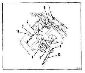
INSTALL PYLON LEFT LOWER BELLCRANK STA 534
(Continued)
11-257
1.
Position bellcrank (1) in support (2) with arrow
(3) forward and arrow (4) up. Install bolt (5),
two washers (6 and 7), and nut (8) in support.
Remove tag.
2.
Torque nut (8) to 85 to 125 inch-pounds. Align
cotter pin hole.
3.
Check bellcrank (1) as follows:
a.
Apply force to end of arm (9). Use dial
indicating scale (10). Bellcrank must rotate
with force less than 3 pounds and bolt (5)
must not turn. If bolt turns, go to step b. If
bolt does not turn, go to step 4.
b.
Back off nut (8) until bolt does not turn when
bellcrank is rotated. Check cotter pin hole
is aligned.
c.
Check that nut torque is more than 85
inch-pounds with cotter pin hole aligned.
d.
Repeat step a.
4.
Install cotter pin (11).
INSPECT
5.
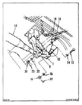
Position connecting link (12) in aft arm (9) of
bellcrank (1). Install bolt (13), two washers (14
and 15), and nut (16).
6.
Position connecting link (17) in bellcrank (1).
Install bolt (18), two washers (19 and 20) and
nut (21).
7.
Torque two nuts (16 and 21) to 60 to 90
inch-pounds. Install cotter pins (22 and 23).
8.
Check two bolts (13 and 18). Bolts shall not
rotate with torque less than 10 inch-pounds.
There shall be no axial looseness. If bolt rotates
or is loose, add washer under nut, and repeat
step 7.
NOTE
If connecting links are changed in
length, perform neutral rig check
(Task 11-33).
FOLLOW-ON MAINTENANCE:
Connect servocylinder connecting links (Task
11-193).
Remove safety blocks (Task 11-29).
Close cargo ramp (Task 2-2).
END OF TASK
11-989