TM 55-1520-240-23-7
9-1
DIRECT CURRENT (DC) POWER DISTRIBUTION SYSTEM
(Continued)
9-1
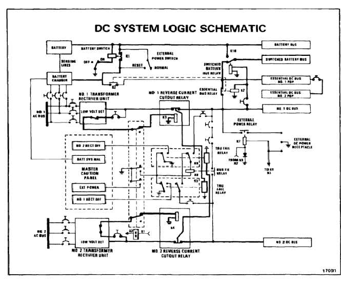
THEORY OF OPERATION
When 115/200 volt 400 Hz ac power is available to the
No. 1 and No. 2 transformer-rectifiers, the No. 1 and
No. 2 dc power sources become available. Each source
provides 28 vdc to its respective dc bus and can supply
up to 200 amperes.
RCCO RELAY
Each transformer-rectifier (TR) is protected against a
reverse flow of current from the helicopter dc bus by
a reverse current cutout (RCCO) relay. Relay 161K3
protects the No. 1 TR and relay 161K4 the No. 2 TR.
NO BREAK - WORK HARDER
In normal operations, 28 vdc power from the TR is
routed from the GEN to the BATT terminals of the relay
through an internal main contactor. The control of this
internal main contactor is provided by a low voltage
detection circuit within the TR.
NO BREAK - WORK HARDER
If this low voltage detection circuit determines that TR
output is acceptable, 28 vdc is routed thru the TR to the
APP terminal of the RCCO, energizing the internal main
contactor and connecting the TR to the dc bus.
NO BREAK - WORK HARDER
If this low voltage detector circuit determines that TR
output is not acceptable, no TR output is applied to
the RCCO APP terminal. As a result the internal main
contactor is not energized isolating the TR from the dc
bus. When this happens, TR failure relay 161K5 (No. 1)
or 161K6 (No. 2) is de-energized, lighting the relevant
RECT OFF light on the master caution panel and
energizing dc bus tie relay 161K8. Energizing 161K8
connects the No. 1 and No. 2 dc buses, allowing both
to be powered by the operating TR.
9-13


