TM 55-1520-240-23-7
8-1
ENGINE INSTRUMENTS
(Continued)
8-1
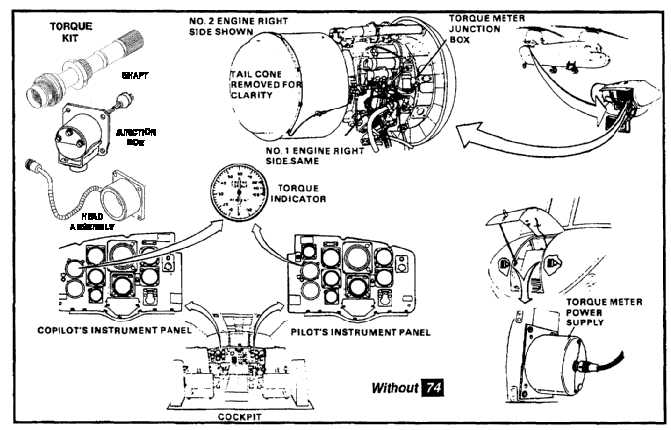
TORQUE INDICATING SYSTEM WITHOUT 74
Description
The torque indicating system, which monitors engine
power output, is a ratio system. It measures and
indicates the amount of engine torque. The system
consists of an engine-driven power shaft, a head
assembly and a junction box on each engine, a dual
torque indicator on each pilot’s instrument panel, and
two power supplies in the nose compartment.
NO BREAK - WORK HARDER
The head assembly and the power shaft make up a
transformer. The head assembly contains the single
primary and two secondary windings of the transformer.
The power shaft is the core of the transformer. The
junction box provides interconnection between system
components. The head assembly, power shaft, and
junction box make up a calibrated set. If one part is bad,
all three must be replaced with a matched set.
NO BREAK - WORK HARDER
A signal from the torquemeter power supply is applied
to the primary winding in the head assembly. With no
engine torque developed, equal signals are coupled
to the secondary windings. When engine torque is
developed, the power shaft is distorted, and unequal
signals are coupled to the secondaries. The signals
from the secondaries are rectified in the indicator and
moves the pointer to show percentage of rated torque.
NO BREAK - WORK HARDER
The indicator is calibrated 0 to 150 percent and has
two numbered pointers, one for each engine. Electrical
connections are provided through two connectors at the
rear of the clamp mounted indicators.
NO BREAK - WORK HARDER
The torquemeter power supply is a solid-state inverter
that converts dc voltage to ac voltage for use by the
engine torque sensor (head assembly).
8-10