TM 55-1520-240-23-6
7-98
TEST PITCH, ROLL, YAW, OR THRUST INTEGRATED LOWER CONTROL ACTUATOR
(ILCA) (AVIM) (Continued)
7-98
90.
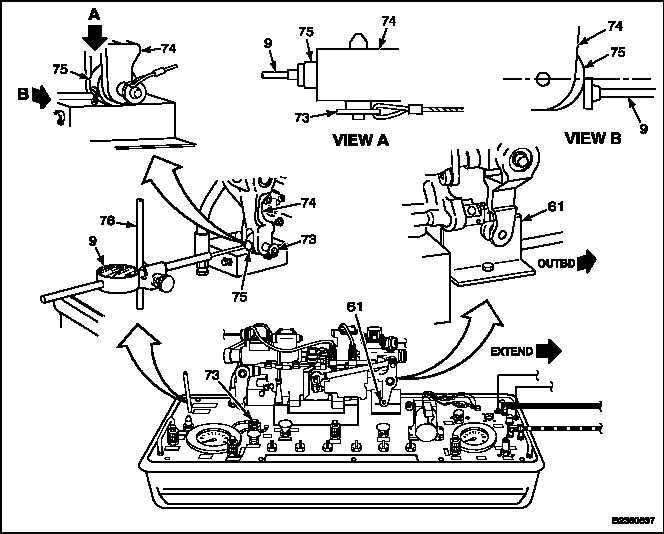
Remove PIN 3 (73) and bearing 145GS278-17
(75) from stowage. Install bearing in output arm
(74).
91.
Install PIN 3 (73) through bearing (75) and arm
(74).
92.
Set arm (74) to full retract stroke. Move arm (61)
fully outward (EXTEND).
93.
Install dial indicator (9) facing up, on post (76).
NOTE
Minimize axial motion when loading
the dial indicator to reduce dial
reading error due to shaft movement.
94.
Set anvil of dial indicator (9) in full contact with
bearing (75), and parallel with face of bearing.
Align top of anvil with center of pin (73). Adjust
outer ring of indicator to zero.
95.
Preload dial indicator (9) to read 0.40 inch.
96.
Deleted.
97.
Deleted.
98.
Deleted.
99.
Manually move input arm (61) to full retract
position. Record dial indicator (9) reading.
100.
Manually move input arm (61) to full extend
position. Record dial indicator (9) reading.
101.
Subtract step 100 reading from step 99 reading.
Travel must be 4.469 to 4.531 inches.
NOTE
If travel is not within limits, the ILCA
must be rigged.
7-428
Change 1


