TM 55-1520-240-23-6
7-98
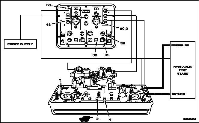
TEST PITCH, ROLL, YAW, OR THRUST INTEGRATED LOWER CONTROL ACTUATOR
(ILCA) (AVIM) (Continued)
7-98
59.19. Set SYSTEM SELECT switch (43) to SAS 2.
59.20. Set SAS PRESS SYS 1 valve (3) to VENT.
59.20.1. Turn SAS PRESS SYS 2 valve (4) to PRESS.
59.21. Turn SAS 2 VALVE CONTROL (35) to EXTEND
until DVM (58) indicates 1.0 volt. SAS 2 NULL
METER (60.2) must move to the right, indicating
10 ±2 microamp. If null meter moves to the left,
SAS 2 is out-of-phase.
NOTE
If null meter moves to the left, check
extensible link wire connections (Task
7-88.1, step 7). If connector is wired
correctly, replace self LVDT (Task
7-88.1).
59.22. Set SAS 2 LINK TEST switch (39) to CROSS
FDBK. DVM (58) must indicate 0.50 ±0.03
volt. If null meter moves to the left, the ILCA is
out-of-phase.
NOTE
If null meter moves to the left, check
extensible link wire connections for
the cross feedback transducer. If
connector is wired correctly, replace
cross feedback transducer (Task
7-88).
59.23. Set SAS 2 FEEDBACK SELECT switch (33) to
CROSS. NULL METER (60.2) must decrease to
5 ±1 microamp. If null meter moves to the left,
SAS 2 ILCA is out-of-phase.
NOTE
If null meter moves to the left, check
extensible link wire connection for
the cross feedback transducer. If
connector is wired correctly replace
cross feedback transducer (Task
7-88).
59.24. Set SAS 2 FEEDBACK SELECT switch (33) to
SELF.
59.25. Set SAS 2 LINK TEST switch (39) to SELF.
59.26. Turn SAS 2 VALVE CONTROL (35) to RETRACT
until DVM (58) indicates 1.0 volt. SAS 2 NULL
METER (60.2) must move to the left, indicating
10 ±2 microamp.
NOTE
If null meter moves to the right, check
extensible link wire connections (Task
7-88.1, step 7). If connector is wired
correctly, replace self LVDT (Task
7-88.1).
Change 1
7-421