TM 55-1520-240-23-6
7-55
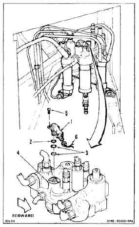
INSTALL NO. 1 OR NO. 2 POWER CONTROL MODULE PUMP CHANGE
INDICATOR
(Continued)
7-55
NOTE
There are two pump change
indicators, one in No. 1 and one in
No. 2 module. Procedure is same
to install any pump change indicator.
No. 1 module is shown here.
1.
Install indicator (1), retainer (2), and two packings
(3) in module (4).
2.
Install three screws (5) in indicator (1).
3.
Lockwire screws (5). Use lockwire (E231).
4.
Install connector (6) on indicator (1).
5.
Lockwire connector (6). Use lockwire (E231).
INSPECT
FOLLOW-ON MAINTENANCE:
Service flight control system (Task 1-60, 1-61, 1-62,
or 1-63).
Perform operational check (TM 55-1520-240-T).
Close right forward work platform or right pylon
access door (Task 2-2).
END OF TASK
7-271

