TM 55-1520-240-23-6
7-318
FLUSH NO. 1 AND NO. 2 PTU AND CARGO HOOK RETURN TUBING
(Continued)
7-318
25.
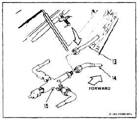
Working from center tunnel, disconnect tube (14)
from hook release valve (15).
26.
Connect hose (13) to valve (15).
Do not exceed 500 psi. Otherwise,
damage to components can occur.
Keep test stand bypass valve closed.
Otherwise, contaminants could
re-enter the system.
27.
Apply hydraulic power. Set stand to 10 gpm at
500 psi. Flush system for 15 minutes. Check
for leaks.
28.
Remove hydraulic power.
29.
Disconnect hose (13) from valve (15). Use
container and cloths (E135) for spilled fluid.
30.
Connect tube (14) to valve (15).
INSPECT
31.
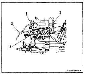
Working from ramp, disconnect hose (3) from
tube (1). Use container and cloths (E135) for
spilled fluid.
32.
Connect tube (1) to PTU RTN port (16) of control
module (2).
INSPECT
FOLLOW-ON MAINTENANCE:
Perform operational check of No. 1 and No. 2 PTU
and cargo hook system (TM 55-1520-240-T).
Close forward work platforms (Task 2-2).
Close tunnel access doors (Task 2-2).
Install forward transmission aft fairing (Task 2-68).
Close aft left access panel (Task 2-2).
END OF TASK
7-1145