TM 55-1520-240-23-4
5-75.1
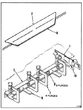
CHECK AND ADJUST ROTOR BLADE TRIM TAB ANGLE
(Continued)
5-75.1
NOTE
Cusp clamp and trim tab clamp must
be installed as a unit.
c.
If trim tab clamp (6) is not nested in cusp
clamp (5), open C-clamps (7) and position
trim tab clamp inside jaws of C-clamps.
d.
Install cusp clamp (5) and trim tab clamp
(6) over trim tab (2). Check that UPPER
AIRFOIL markings are facing up.
e.
Ensure that cusp clamp (5) is firmly seated
against blade trailing edge. Tighten C-clamps
(7).
f.
Ensure that trim tab clamp (6) is centered
and fully seated against trim tab trailing edge
(8). Tighten hand wheels (9).
g.
Install angle indicator assembly (1) on
outboard end of trim tab clamp (6). Scale of
angle indicator shall be next to pointer
NOTE
Maximum trim tab bend angle up or
down is 15º from zero.
h.
Using handles on trim tab clamp (6), bend
trim tab (2) slightly past then desired angle.
Release the handles and allow the tab to
spring back. Read the new bend angle on
pointer (10) at the scale of angle indicator (1).
i.
Repeat step h until you get the required
angle.
j.
Loosen clamps (7 and 8). Remove cusp
clamp (5) and trim tab clamp (6) from rotor
blade.
7.
Remove angle indicator assembly (1).
NOTE
Any adjustment made on the trim tab,
different from the stenciled angle on
the blade shall be logged on the DA
Form 2408-16 Component Historical
Record.
FOLLOW-ON MAINTENANCE:
Remove tiedown lines from blades (Task 1-26).
END OF TASK
5-431