TM 55-1520-240-23-4
5-75.1
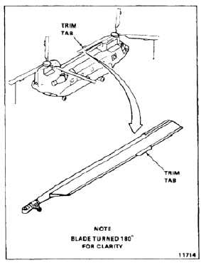
CHECK AND ADJUST ROTOR BLADE TRIM TAB ANGLE
5-75.1
INITIAL SETUP
Applicable Configurations:
All
Tools:
Trim Tab Bending and Indicating, Fixture
145G1019-29
Materials:
None
Personnel Required:
Medium Helicopter Repairer
Inspector
Equipment Condition:
Battery Disconnected (Task 1-39)
Electric Power Off
Hydraulic Power Off
Blade Positioned Over Tunnel, One Forward and One
Aft Blade Tied Down (Task 1-26)
NOTE
Trim tab bending and indicating
fixture 145G1019-29 contains
the following assemblies:
145G1019-32 Angle Indicator Assy
145G1019-30 Cusp Clamp Assy
145G1019-31 Trim Tab Clamp Assy
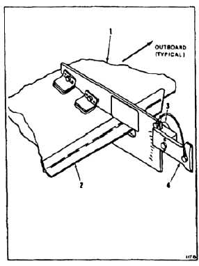
1.
Install angle indicator assembly (1) on blade
fairing about four inches inboard of the outboard
end of trim tab (2).
2.
Loosen thumb screw (3), clamping trim tab
checking assembly (4) on angle indicator (1).
5-429