TM 55-1520-240-23-4
5-62
ROTARY-WING BLADES
(Continued)
5-62
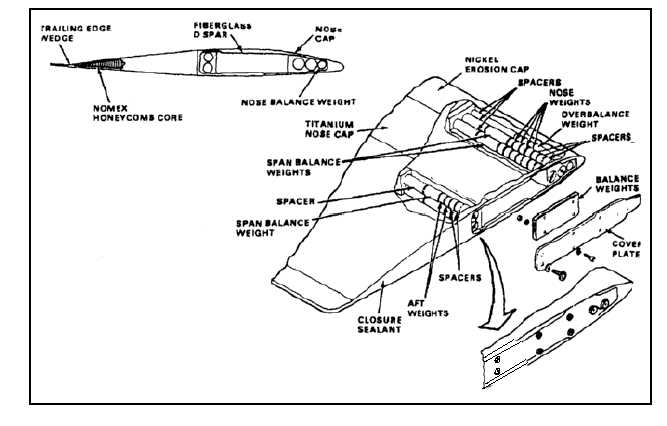
TRACKING AND BALANCE WEIGHTS
Each blade has tracking and balance weights installed in
its tip. The weights are reached by removal of the cover
plate. A maximum of 10 balance weights are attached
to the inside of each cover plate. These weights are
added or removed for AVA balancing requirements. The
tracking weights are located in capped tubes behind
the cover plate. Three tubes are in the leading edge
section of the spar. Two tubes are positioned at the aft
end of the spar. Weights are moved to compensate for
the weight of blade repairs. Targets are installed on the
cover plate before blade tracking.
LIGHTNING PROTECTION
Wire mesh is installed near the surface of the skin for
lightning protection. The mesh reaches to the trailing
edge of the blade at the trim tab and at the tip. The
mesh goes to the nosecap which provides a path to the
jumper wires at the top and bottom of the blade spar at
the inboard end. These jumper wires are connected to
the oil manifold tube on the pitch housing.
TRIM TAB
The rotor blade trim tab is bent at the factory to the
correct angle for the blade. The tab is bent to a position
where it remains to keep the blade in the desired trim.
Adjustment of the trim tab on the rotor blade changes
the blade to a corrected angle to maintain a given track
or plane of motion.
END OF TASK
5-271/(5-272 blank)