TM 55-1520-240-23-3
4-157
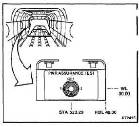
INSTALL POWER ASSURANCE PANEL AND TEST SWITCH
4-157
INITIAL SETUP
Applicable Configurations:
With 74
Tools:
Electrical Repairer’s Tool Kit, NSN 5180-00-323-4915
Ohmmeter
Materials:
Paper Tags (E264)
Personnel Required:
Aircraft Electrician
References:
TM 9-6625-975-35
TM 55-1520-240-T
Equipment Condition:
Battery Disconnected (Task 1-39)
Electrical Power Off
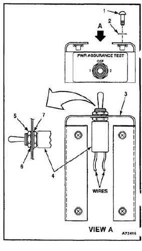
1.
Position switch (4) and lockring (7) on panel (3).
2.
Install lockwasher (6) and nut (7) on the switch
(4).
3.
Attach the wires to the switch (4). Discard the
tags.
4.
Position the panel (3) and install the washers (2)
and screws (1).
5.
Perform bonding and grounding check per
TM 9-6625-975-35. The maximum resistance
between the switch (4) and the panel (3) is
0.0025 ohms.
FOLLOW-ON MAINTENANCE:
Perform the operational check of the power assurance
test switch (TM 55-1520-240-T).
END OF TASK
4-513