TM 55-1520-240-23-3
4-135
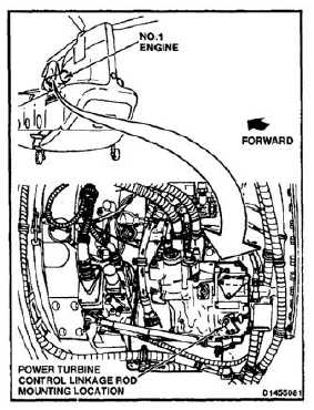
INSTALL POWER TURBINE CONTROL LINKAGE ROD
4-135
INITIAL SETUP
Applicable Configurations:
Without
74
Tools:
Powerplant Repairer’s Tool Kit, NSN
5180-00-323-4944
Torque Wrench, 30 to 150 Inch-Pounds
Measuring Tape
Materials:
Lockwire (E229)
Parts
Cotter Pins
Personnel Required:
Aircraft Powerplant Repairer
Inspector
References:
TM 55-1520-240-23P
NOTE
Procedure is same to install power
turbine control linkage rod on No. 1
or No. 2 engine. Installation of No. 1
rod is shown here.
1.
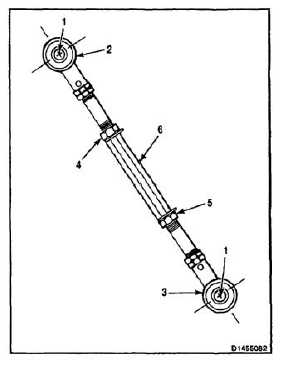
Measure distance between centers of holes
(1) in rod ends (2 and 3). If length is same as
dimension A found in removal, go to step 2. If
length is not same, do the following:
a.
Loosen nuts (4 and 5).
b.
Rotate turnbuckle (6) until distance between
holes (1) in rod ends (2 and 3) is same as
dimension A found in removal.
c.
Make sure rod ends (2 and 3) are aligned.
d.
Tighten nuts (4 and 5).
NOTE
Nominal distance between centers
of holes in rod ends is 10-17/32 to
10-9/16 inches.
Do not lockwire nuts at this time.
4-445