TM 55-1520-240-23-11
17-6
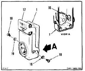
ASSEMBLE EMERGENCY EXIT LIGHT
(Continued)
17-6
11.
Position bar (handle) (17) on housing (1). With
bar in closed position, flat side of adapter (10)
shall be parallel to edge of housing (1).
12.
Install two screws (18) and washers (19).
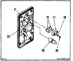
INSTALL CIRCUIT BOARD
13.
Position circuit board (20) on base (21). Solder
three contacts (22). Use solder (E360).
14.
Install two screws (23), four washers (24), and
two retaining rings (25).
INSTALL LAMPS
15.
Install two lamps (26) in holder (27).
16.
Install holder (27), washer (28), and screw (29)
in circuit board (20).
17.
Install main lamp (30) in holder (31).
17-17