TM 55-1520-240-23-9
11-56
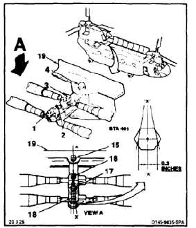
RIG TUNNEL CONTROLS LINKAGE
(Continued)
11-56
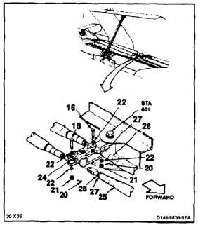
4.
Working in tunnel section check four bolts (15,
16, 17, and 18) sta. 401. Bolts must align and
be parallel to line ‘X’ - ‘X’, 90º to surface (19) to
within 0.03 inch. If aligned go to step 11. If not
perform steps 5 thru 8. Use combination square.
5.
Remove two cotter pins (20), nuts (21), washers
(22), and two bolts (18 and 16) from idler arm
(24). Disconnect links (25 and 26) from arm.
6.
Loosen nut (27) of links (25 and 26). Turn device
(28) one complete turn. Turn clockwise to move
end of arm (24) forward.
NOTE
One turn of device moves end of arm
about 0.02 inches.
7.
Position links (25 and 26) in arm (24). Install
bolts (16 and 18), washers (22), and nuts (21).
Tighten nuts.
8.
Repeat step 4. If aligned perform step 9. If not
repeat steps 5 thru 8.
9.
Torque nuts (27) of links (25 and 26) to the
following values:
NO BREAK - WORK HARDER
Jam nut AN316-6R to 103 inch-pounds.
Jam nut AN316-7R to 285 inch-pounds.
10.
Torque nuts (21) to 60 to 90 inch-pounds.
Install cotter pins (20).
11.
Check bolts (16 and 18). Bolt shall not rotate
with torque less than 10 inch-pounds. Bolt shall
have no axial looseness. If bolt rotates or is
loose, add washer under nut and repeat step 10.
11-257