TM 55-1520-240-23-7
8-19
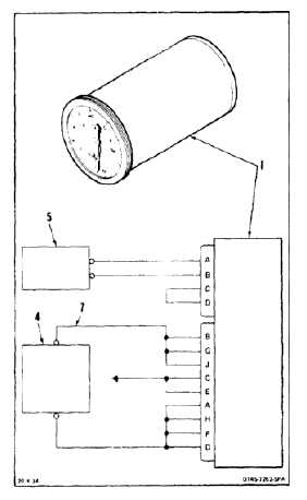
TEST DUAL TORQUEMETER INDICATOR (AVIM)
(Continued)
8-19
9.
Connect 1 MA lead (7) to meter test set (4).
10.
Apply power to power supply (5).
NOTE
When testing No. 1 pointer of
indicator, No. 2 pointer will also move.
Ignore No. 2 pointer until test of No. 1
is complete.
11.
Adjust meter test set (4) DIRECT CURRENT
COURSE and DIRECT CURRENT FINE controls
to obtain indicator (1) settings as indicated
below. For indicator setting listed test set
MICROAMPERE reading shall be within range
as listed below:
NO BREAK - WORK HARDER
TORQUEMETER
INDICATOR
READING
TS-682A/GSM-1 DC
MICROAMPERE
RANGE (UA)
10
51 to 63
20
117 to 129
40
277 to 289
60
450 to 462
80
599 to 611
100
694 to 706
150
813 to 825
12.
Repeat step 11 and check indicator (1) pointer
No. 2. Meter test set (4) readings shall be within
tolerance as listed in step 11.
13.
Adjust meter test set (4) DIRECT CURRENT
COURSE and DIRECT CURRENT FINE to 0 dc
(TM 11-6625-277-14).
14.
Shutdown power supply (5).
15.
Disconnect indicator (1) from test setup.
FOLLOW-ON MAINTENANCE:
None
END OF TASK
8-63