TM 55-1520-240-23-7
9-7
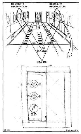
INSTALL DC CABIN UTILITY RECEPTACLE
9-7
INITIAL SETUP
Applicable Configurations:
All
Tools:
Electrical Repairer’s Tool Kit, NSN 5180-00-323-4915
Materials:
None
Personnel Required:
Aircraft Electrician
Inspector
References:
TM 55-1520-240-23P
Positive wire must be connected to
positive terminal; otherwise, damage
to support equipment or fire may
result.
NOTE
Procedure is same to install any dc
utility receptacle.
Small terminal (brass colored) is
positive.
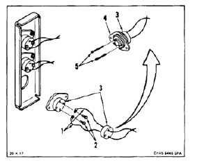
1.
Remove tape and connect two wires (1) by
installing two screws (2). Remove tags.
2.
Position cover (3) on receptacle (4). Install two
screws (5).
9-31