TM 55-1520-240-23-7
8-89
INSTALL CLAMP MOUNTED INSTRUMENTS IN PILOT’S OR COPILOT’S INSTRUMENT
PANEL
(Continued)
8-89
Be careful when handling indicators.
Rough handling will damage
indicators.
NOTE
Procedure is similar for installing
pilot’s and copilot’s Dual Torquemeter
Indicator or Rotor Tachometer.
Installation of copilot’s Dual
Torquemeter Indicator is shown here.
Intermixing of P/N 114ES270-3 and
P/N 114ES270-4 on the same aircraft
is not allowed.
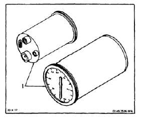
1.
Clean bonding surface of indicator (1). Use cloth
(E120).
2.
Check indicator (1) for range marks. Apply range
marks and index mark to indicator if required (TM
55-1520-240-10 and TM 55-6600-200-20).
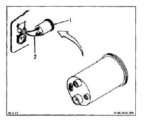
3.
Connect wire harness connector (2) (two
connectors on dual torquemeter) to indicator (1).
8-284