TM 55-1520-240-23-7
8-1
ENGINE INSTRUMENTS
(Continued)
8-1
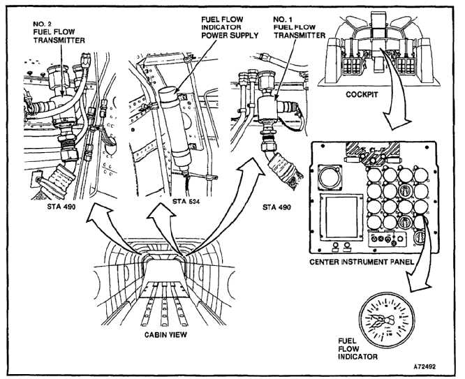
FUEL FLOW INDICATING SYSTEM
Description
This system consists of a fuel flow indicator, a power
supply, and two transmitters, one for each engine.
NO BREAK - WORK HARDER
The fuel flow indicator, clamp mounted on the center
instrument panel indicates fuel flow in pounds per
hour (PPH). The power supply provides power to
both transmitters, which are located below the engine
disconnect shelves, both sides, aft cabin.
NO BREAK - WORK HARDER
The fuel flow indicator power supply furnishes power to
the transmitter motor, the rotor of which is an impeller.
The impeller is driven at a constant angular velocity. As
fuel passes through the impeller it picks up the angular
velocity of the impeller.
NO BREAK - WORK HARDER
The fuel strikes a spring restrained stator causing the
stator to rotate in proportion to the flow rate. The change
in angular rotation is measured by a synchro connected
to the stator.
NO BREAK - WORK HARDER
The synchro signal is applied to a receiver synchro in
the fuel flow indicator and displays the fuel flow rate in
pounds per hour (PPH).
END OF TASK
8-13/(8-14 blank)