TM 55-1520-240-23-7
8-80.5.1
TEST AND ADJUST FUEL QUANTITY INDICATOR USING PSD 60-1AF FUEL QUANTITY
TEST SET
(Continued)
8-80.5.1
8.
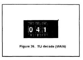
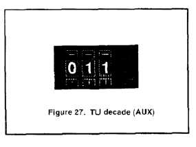
Set the TU decade (D-1) on tester to read "041"
if calibrating a MAIN TANK, and to "011" if
calibrating an AUX TANK (Figures 26 and 27).
9.
Subtract cable LOZ-HIZ capacitance measured
in Section A, step 13 from "ADDED" capacitance
listed in Table 1 for this tank.
10.
Adjust TU vernier (V-1) until LCD reads
capacitance calculated in step 9.
11.
Verify that (P-2) is connected to tank-wall
connector if calibrating a MAIN TANK, and that
(P-1) is connected if calibrating an AUX TANK.
12.
Rotate FUNCT switch (S-2) to AIRCRAFT ONLY.
13.
If calibrating Refueling Panel gauge, disconnect
plug from gauge, remove gauge from panel, and
reconnect plug to gauge.
14.
Connect and turn ON AGPU, or turn ON aircraft
APU to supply electrical power.
15.
Close the following circuit breakers on No. 1
PDP:
CAUTION PANEL
XFMR RECT
REV CUR CO
FUEL QTY
FUEL QTY XFEED CONTROL
REFUEL
16.
Deleted.
17.
If calibrating a Fueling Panel gauge, switch
REFUEL STATION switch on cockpit Fuel Control
Panel to ON. Switch PWR ON-OFF switch on
Refueling Panel to ON.
18.
Select tank to be calibrated on Fuel Quantity
Select switch.
8-249