TM 55-1520-240-23-7
8-45
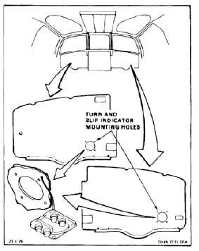
INSTALL TURN AND SLIP INDICATOR IN PILOT’S OR COPILOT’S INSTRUMENT PANEL
8-45
INITIAL SETUP
Applicable Configurations:
Without 17
Tools:
Electrical Repairer’s Tool Kit, NSN 5180-00-323-4915
Materials:
Cloth (E120)
Personnel Required:
Aircraft Electrician
Inspector
References:
TM 55-1520-240-23P
TM 55-6600-200-20
TM 55-1500-323-25
Be careful when handling indicators.
Rough handling will damage
indicators.
NOTE
Procedure is same for installing pilot’s
or copilot’s turn and slip indicator.
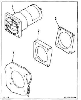
1.
Clean bonding surfaces of indicator (1) mounting
plates (2 and 3) and instrument panel (4). Use
cloth (E120) (TM 55-1500-323-25).
8-134