TM 55-1520-240-23-5
6-10
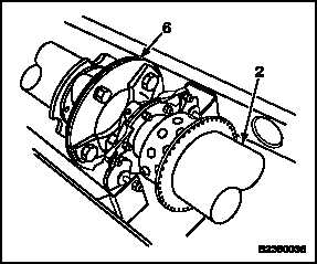
INSPECT DRIVE SHAFTING ON AIRCRAFT (Continued)
6-10
h.
Cracks in plates (6). Use a 5X magnifying
glass to check. If a crack is suspected in
drive shaft plate, refer to TM 1-1520-253-23.
i.
Nicks on inside edge of plates (6). Use a
pointed scribe to check.
j.
Cracks, nicks, scratches, or gouges in dents
in tube (2). Use a 3X to 5X magnifying glass
for inspection. If a crack is suspected in drive
shaft tube, refer to TM 1-1520-253-23.
NOTE
Vibro-engraved factory markings on
tube are allowed.
k.
Inspect for corrosion. If found, perform Task
6-10.1.
2.
Inspect for nicks, scratches, or gouges in tube (2)
and plates (6). Repair damage (Task 6-11).
3.
Visually inspect tubes (2) for circumferential
scoring. Observe following limits:
a.
Depth after blending: 0.010 inch maximum.
b.
Length after blending: 2.0 inches maximum.
c.
Width after blending: 0.40 inch maximum.
d.
Minimum distance from adapter rivets is: 7
inches each end.
e.
Minimum axial distance between
circumferential scoring repair is 4.5 inches.
f.
Maximum of one circumferential scoring
repair around tube OD at any one point.
Change 1
6-31