TM 55-1520-240-23-3
4-153
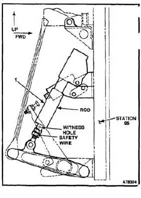
INSTALL AND RIG THRUST CONTROL POSITION TRANSDUCER
ASSEMBLY
(Continued)
4-153
25.
If the voltages do not fall within those specified in
the table, remove the safety wire, and adjust the
LVDT until voltage is within range limits.
NOTE
Ensure that the threads of the rod end
can be seen through the witness hole.
If the threads are not visible, a new
rod will be required.
26.
Lockwire the rod end after adjustment is
completed. Use lockwire (E231).
INSPECT
27.
Ensure that the voltage ranges are correct.
Repeat steps 20 thru 24.
4-507