TM 55-1520-240-23-3
4-11.3
REPAIR OF ENGINE ELECTRICAL HARNESS
(Continued)
4-11.3
40.
Replace conduit section C as follows:
a.
Remove connectors (7) (steps 1 thru 6).
b.
Tag wires for each connector (TM
55-1500-323-24).
c.
Disconnect conduit section D and section E
nuts (1) from coned junction plate (15).
d.
Pull connector elbows (3) and conduit
sections D and E off wiring.
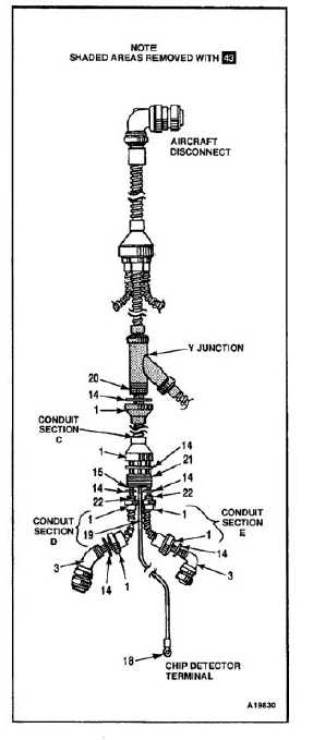
NOTE
With 43 , Y junction and conduit
sections preceding and following Y
junction are replaced by a single
conduit between two coned junctions.
e.
Disconnect nuts (1) of conduit section C from
coned junction plate (15) and V junction.
f.
Remove chip detector terminal (18).
g.
Slide plate (15) and conduit section C off
wiring.
h.
Slide on new conduit section C.
i.
Feed wiring as tagged, through coned
junction plate (15).
j.
Apply shrink tubing (E431) to chip detector
wire (19) where it goes through junction
plate (15). Apply sealant (E340.2) to wire on
section C side of plate.
k.
Apply sealant (E340.2) to threads (20) of Y
junction, and threads (21) of coned junction.
l.
Position nylon washers (14) and connect
conduit section C conduit nuts (1) to Y
junction threads (20) and coned junction
threads (21).
m.
Install conduit sections D and E over wiring.
n.
Install conduit nuts (1), elbows (3), and
connectors (7) (steps 7 thru 17).
4-91