TM 55-1520-240-23-9
11-249
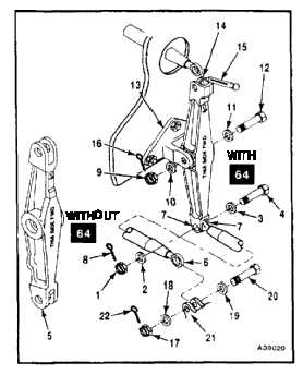
INSTALL AFT FUSELAGE BELLCRANK (FORWARD SIDE STATION 482
BULKHEAD)
(Continued)
11-249
Bushings must be in bellcrank before
installing bolts; otherwise, damage to
components will result.
NOTE
Impedance bolts are installed in flight
control connections. These bolts are
self-retaining and require a special
nut and torque (Task 1-13).
1.
Remove nut (9), two washers (10 and 11), and
bolt (12) from support (13).
NOTE
If bellcrank is not properly marked,
measure the distance between center
hole and two end holes in bellcrank.
Without 64 , mark longer side (6.00
inches) and short side (5.91 inches)
on bellcrank with grease pencil. Place
longer side up and straight side
forward. With 64 , the closed clevis is
up with the closed side forward.
2.
Install bolt (12), two washers (11 and 10), and
nut (9).
3.
Torque nut (9) to 250 inch-pounds.
4.
Check bellcrank (5) as follows:
a.
Back off torque to at least 100 inch-pounds
and apply force to end of arm (14). Use dial
indicating scale (15). Bellcrank must rotate
with force less than 3 pounds and bolt (12)
must not turn. If bolt turns, go to step b. If
bolt does not turn, go to step 10.
b.
Back off nut (9) until bolt does not turn when
bellcrank is rotated. Check cotter pin hole
is aligned.
c.
Check that nut torque is more than 100
inch-pounds with cotter pin hole aligned.
d.
Repeat step a.
5.
Install cotter pin (16).
6.
Remove nut (1), two washers (2 and 3), and bolt
(4) from bellcrank (5).
11-966