TM 55-1520-240-23-9
11-241
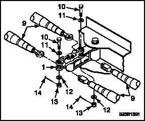
INSTALL TUNNEL CONTROL ARMS (Continued)
11-241
4.
Position four connection links (9) in control arm
(1).
5.
Install two bolts (10), two washers (11), and
two nuts (13). Torque two nuts 60 to 90
inch-pounds. Install two cotter pins (14).
6.
Check bolts (10). Bolts shall not rotate with
torque less than 10 inch-pounds. Bolts shall
have no axial looseness. If bolts rotate or are
loose, add washer under nut and repeat step 5.
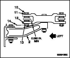
7.
Check clearance between bolt (10) and idler
(2). Clearance shall be 0.060 inch minimum. If
clearance is more than 0.060 inch, go to step 11.
If clearance is less than 0.060 inch, go to step 8.
WARNING
Epoxy primer (E292.1) is flammable
and toxic. It can irritate skin and
cause burns. Use only with adequate
ventilation, away from heat and
open flame. Avoid contact with skin,
eyes, or clothing. In case of contact,
immediately flush skin or eyes with
water for at least 15 minutes. Get
medical attention for eyes.
8.
Remove cotter pin (14), nut (13), two washers
(12 and 11), and bolt (10). Burnish idler (2) under
bolt hole. Use abrasive paper (E11). Do not
burnish more than 0.040 inch deep and 1 inch in
diameter. There shall be no sharp indentations
or gouges in burnished area. Touch up burnished
area with two coats of epoxy primer (E292.1).
Wear gloves (E184.1).
9.
Install bolt (10), two washers (11 and 12) and nut
(13). Torque nut to 60 to 90 inch-pounds.
10.
Install cotter pin (14). Turn ends of cotter pin
into nut castellations to maintain 0.060 inch
clearance.
11.
Check bolt (10). Bolt shall not rotate with torque
less than 10 inch-pounds. Bolt shall have no
axial looseness. If bolt rotates or is loose, add
washer under nut and repeat steps 9 and 10.
11-937