TM 55-1520-240-23-9
11-124
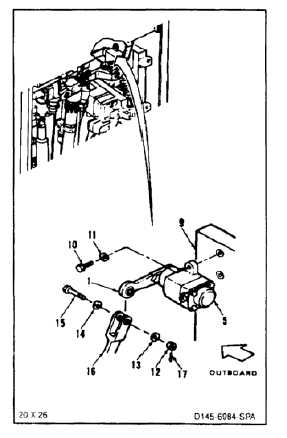
INSTALL THRUST VISCOUS DAMPER
(Continued)
11-124
FLIGHT SAFETY PARTS
This is an installation critical flight
safety part. All aspects of its assembly
and installation must be ensured at
each joint connection and mounting to
the airframe.
Ensure that the correct damper is
installed in the thrust axis. Incorrect
axis orientation will adversely affect
force feel damping characteristics of
the flight control system.
Ensure the proper damper arm
assembly is installed. Arm assembly
has shear rivets sized to specific load
requirements in the event of a damper
failure.
Ensure all hardware mounting the
damper assembly to the pallet
assembly is secure and that there is
no evidence of loose pallet inserts.
Loose attachments within flight control
secondary linkage will degrade
aircraft control, missing components
may cause loss of control.
Bushing must be link before installing
bolt; otherwise, damage to component
will result.
NOTE
Impedance bolts are installed in flight
control connections. These bolts are
self-retaining and require a special
nut and torque (Task 1-13).
7.
Position damper (5) on pallet (9), arm (1)
outboard. Install two bolts (10) and washers (11)
in damper.
7.1.
Torque bolts (10) to 23 inch-pounds.
8.
Remove nut (12), two washers (13 and 14) and
bolt (15) from link (16).
9.
Position arm (1) in link (16). Install bolt (15), two
washers (14 and 13), and nut (12) in link and
arm.
10.
Torque nut (12) to 15 to 25 inch-pounds. Install
cotter pin (17).
11.
Check bolt (15). Bolt shall not rotate with torque
less than 10 inch-pounds. There shall be no
axial looseness. If bolt rotates or is loose, and
washer under nut and repeat step 10.
INSPECT
FOLLOW-ON MAINTENANCE:
Perform thrust control operational check (TM
55-1520-240-T).
Install closet backup panel (Task 2-2).
Install closet acoustic blanket (Task 2-108).
END OF TASK
11-576