TM 55-1520-240-23-9
11-100
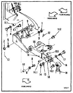
INSTALL PITCH IDLER BELLCRANK
(Continued)
11-100
Bushings must be in bellcranks and
links before installing bolts; otherwise,
damage to components will result.
NOTE
If a crack in the connecting link,
bellcrank, or support is suspected
during installation, refer to TM
1-1520-253-23.
NOTE
Impedance bolts are installed in flight
control connections. These bolts are
self-retaining and require a special
nut and torque (Task 1-13).
1.
Remove two nuts (1 and 2), four washers (3, 4, 5,
and 6) and two bolts (7 and 8) from support (9).
1.1.
Remove bushings (9.1 and 9.2) from support
(9). Clean bushings and bores with dry cleaning
solvent (E162) and clean cloth (E120). Wear
gloves (E184.1) and goggles.
1.2.
Coat bushings (9.1 and 9.2) with epoxy primer
(E292). Install bushings wet in support (9).
FLIGHT SAFETY PARTS
This is an installation critical flight
safety part. All aspects of its assembly
and installation must be ensured at
each joint connection and mounting to
the airframe.
Ensure that all bushings and bearings
are properly installed (including
bushing orientation) in each input and
output clevis of the idler.
Ensure hub bearings are serviceable
and properly installed.
Ensure proper attaching hardware
associated with all components
mounted to this idler assembly and the
idler assembly itself (impedance type
bolt, nut, and washers) is installed
including verification of bolt head
orientation, torque, and installation
of cotter pins.
Loose attachments within flight control
secondary linkage will degrade
aircraft control. Missing components
will cause loss of control.
2.
Position pitch idler bellcrank (10) in support (9),
arm (11) forward and inboard. Install two bolts
(7 and 8), four washers (6, 5, 4, and 3), and two
nuts (1 and 2), in support.
3.
Torque two nuts (1 and 2) to 30 to 45
inch-pounds. Use wrench and dial indicating
scale. Install two cotter pins (12 and 13).
4.
Check bolts (7 and 8). Bolts shall not rotate with
torque less than 10 inch-pounds. There shall be
no axial looseness, if bolt rotates or is loose, add
washer under nut, and repeat step 3.
INSPECT
5.
Remove nut (14), two washers (15 and 16), and
bolt (17) from lugs (18) of bellcrank (10).
5.1.
Remove bushings (10.1 and 10.2) from bellcrank
(10). Clean bushings with dry cleaning solvent
(E162) and clean cloth (E120). Wear gloves
(E184.1) and goggles.
5.2.
Coat bushings (10.1 and 10.2) with epoxy primer
(E292). Install bushings wet in bellcrank (10).
6.
Position pitch input connecting link (19), between
lugs (18) of bellcrank (10). Install bolt (17), two
washers (16 and 15), and nut (14). Do not torque
nut at this time.
11-520